Unidraf GE
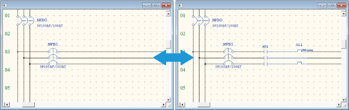
“Expert Model” for pursuing efficiency with high-grade performance
Limited options are standard

Equipped with BOM creation + parts layout.
In addition, the parts symbols for outline drawings can be called from the created bill of materials type and automatically arranged.

Main Functions
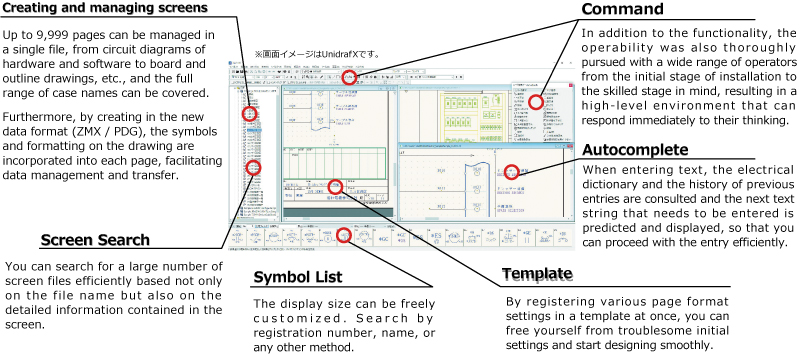
Line trimming function
Placing a symbol on a line automatically cuts the line, and removing the symbol automatically repairs the line.
This completely frees the user from frequent and troublesome tasks such as deleting or redrawing part of a line.
Circuit bar (electric-only command)
Wires single-phase to 4-phase in a batch using the electric circuit dedicated commands wire, bus bar, and OR.
Wiring conditions are determined and intersections are automatically added.

Automatic display of coil references/comments on contacts
Displays the address where the contact is used and the coil number and coil comment for each contact in real time.
Coil references can be selected from “List format,” “End of coil row,” or “List format by AB.
In addition, you can search for a related destination with a simple click operation and quickly jump to the corresponding location.

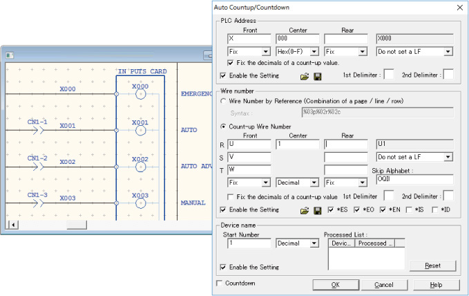
Device name/Wire number/PLC address countup/down
Device name/Wire number/PLC address, each of which is automatically assigned to the specified value in the specified decimal number.
(octal, decimal, hexadecimal (0-F), hexadecimal (0-15), etc.)
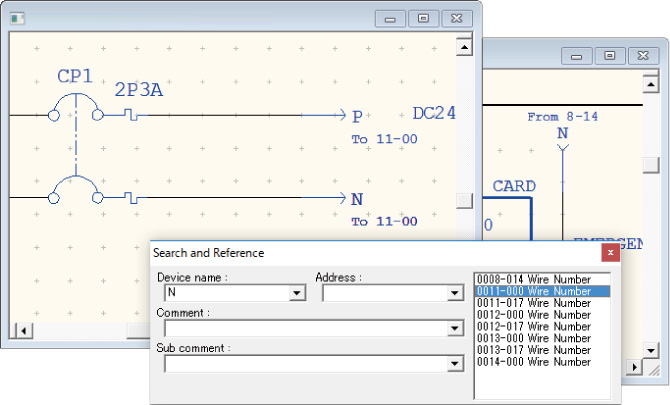
Wiring number reference
By entering a crossing line number, the destination and origin number of that line are displayed in real time.
In addition, you can search for a crossing destination with a simple click operation and quickly jump to the corresponding location.
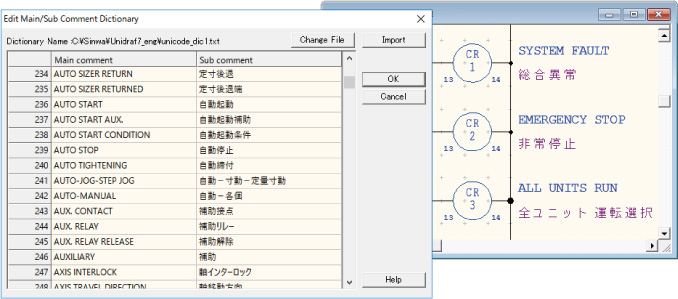
Primary and secondary comment dictionaries
Japanese and foreign languages from around the world (Unicode-compatible) can be registered to automatically fill in foreign languages when entering coil comments.
Multiple dictionaries can be held, so you can switch between them as needed.
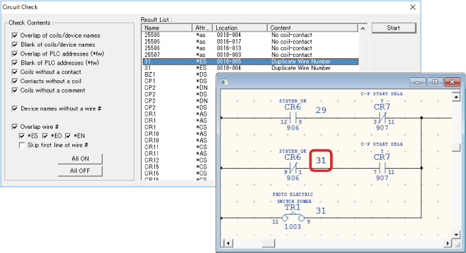
Circuit check
Duplicate wire numbers, duplicate coils, duplicate devices, duplicate PLC addresses, coils with no contacts, contacts with no coils, devices with no comments, devices with no wire numbers, etc. can be searched from the drawing and displayed in a list.
You can also quickly jump to the corresponding section from the search results.
Automatic assignment of device name/wire number from I/O address
When creating input circuits, device names and wire numbers are automatically entered by referencing each PLC address, greatly eliminating labor and errors.

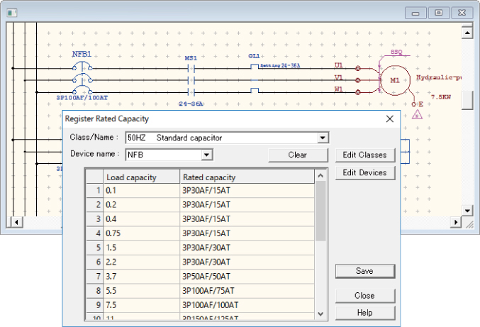
Automatic capacity setting
Capacities are automatically assigned to each device (NFB, MS, etc.) based on the capacity of the motor.
This eliminates simple input errors and allows circuits to be created with a minimum of keystrokes, significantly reducing data entry time.
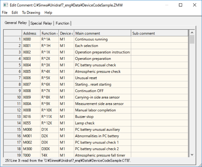
Edit Comment
Easily create and modify comments for input circuits and soft circuits in tabular form.
Data can be passed to and from external parties by copying and pasting, text files, etc., freeing you from having to type comments twice.
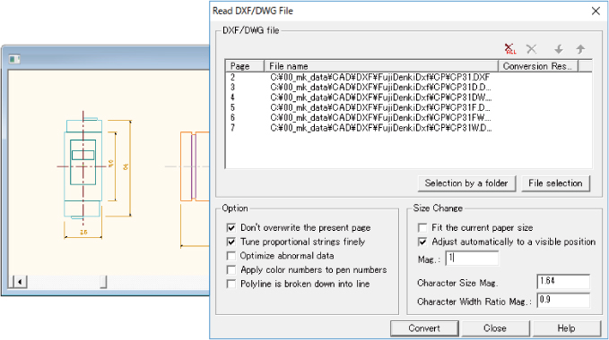
DXF/DWG conversion
Import and export DXF and DWG files essential for data conversion.
Multiple files can be processed at once.
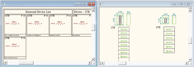
External Device List + automatic creation of external/relay terminals
【External Device List】
External devices such as LS and SOL can be searched from the circuit diagram for device name, name, and wire number information and displayed in a list format in the drawing.
【Automatic creation of external/relay terminals】
The number of terminals for each relay box can be retrieved from the circuit diagram, and the appropriate relay box can be automatically selected and displayed in the drawing.
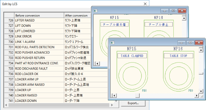
LCS(Language Conversion System)
By using a dictionary file in which the corresponding language of each country is registered, not only comments on coils and I/O diagrams in electric circuits, but also comments in board outline drawings can be replaced by the desired language at once.
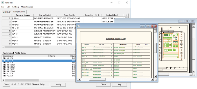
Parts List & Parts Layout
The parts used in a drawing can be picked up and totaled. The results can be extracted to the user’s original bill of materials format or converted to a text file.
In addition, by associating symbols for external shapes with each part format, troublesome layout work can be made more efficient.
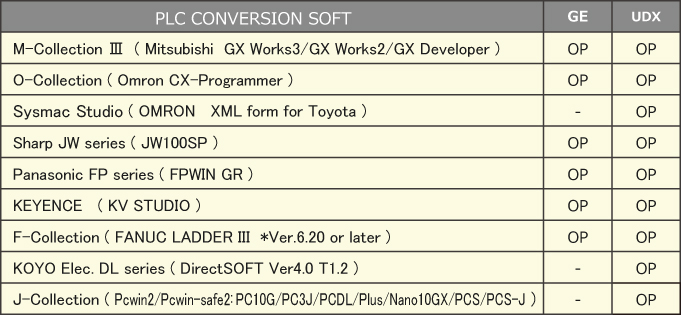
PLC Conversion (OP)
By purchasing the optional PLC Link Software, PLC data and comment data can be read and written.
This enables centralized drawing creation and management, including hardware drawings, input/output schematics, and panel outline drawings.